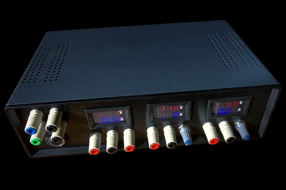
Every electronics engineer should have a“laboratory” power supply in his or her workshop. A power supply of this type is a power supply box that allows several adjustable and/or fixed voltages to be available, with one or more displays indicating the voltage and current consumed by the powered “receiver”. A power supply of this type can be used to test electronic assemblies, motors or devices for which the original power supply is not necessarily available. On average, this type of power supply costs between €400 and €800, depending on the power delivered.
For less than 200€, using a PC ATX power supply, I produced this assembly whose characteristics are as follows:
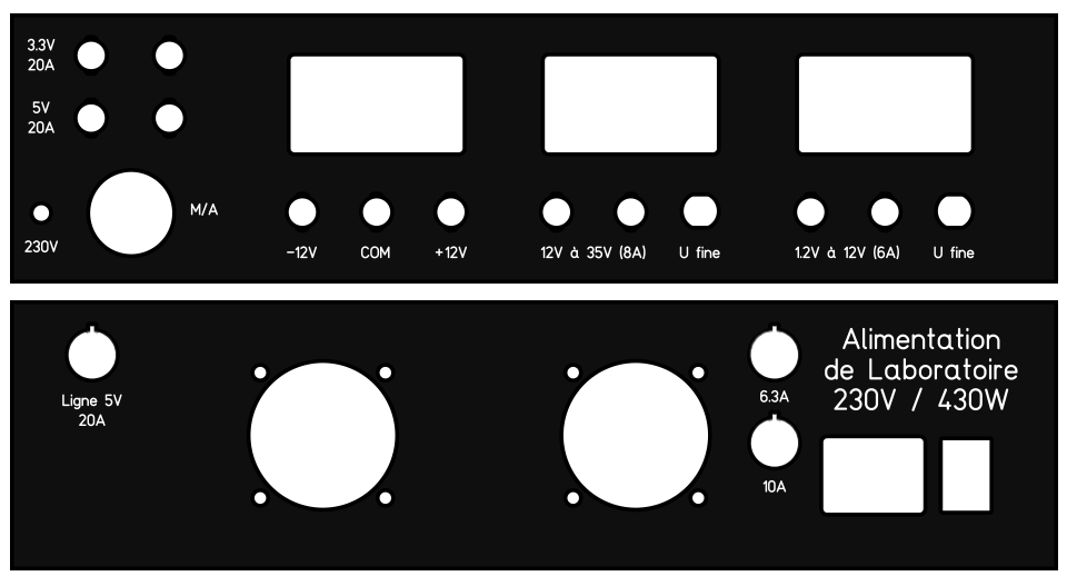
- 1 fixed output -12 V/0/+12 V at 800 mA max (9.6 W)
- 1 output adjustable from 12 V to 35 V at 9 A (max current adjustable via internal potentiometers)
- 1 output adjustable from 1.2 V to 12 V at 6 A max (max current adjustable via internal potentiometers)
- 1 fixed output of 5 V at 20 A max.
- 1 fixed output of 3.3 V at 20 A max (130 W)
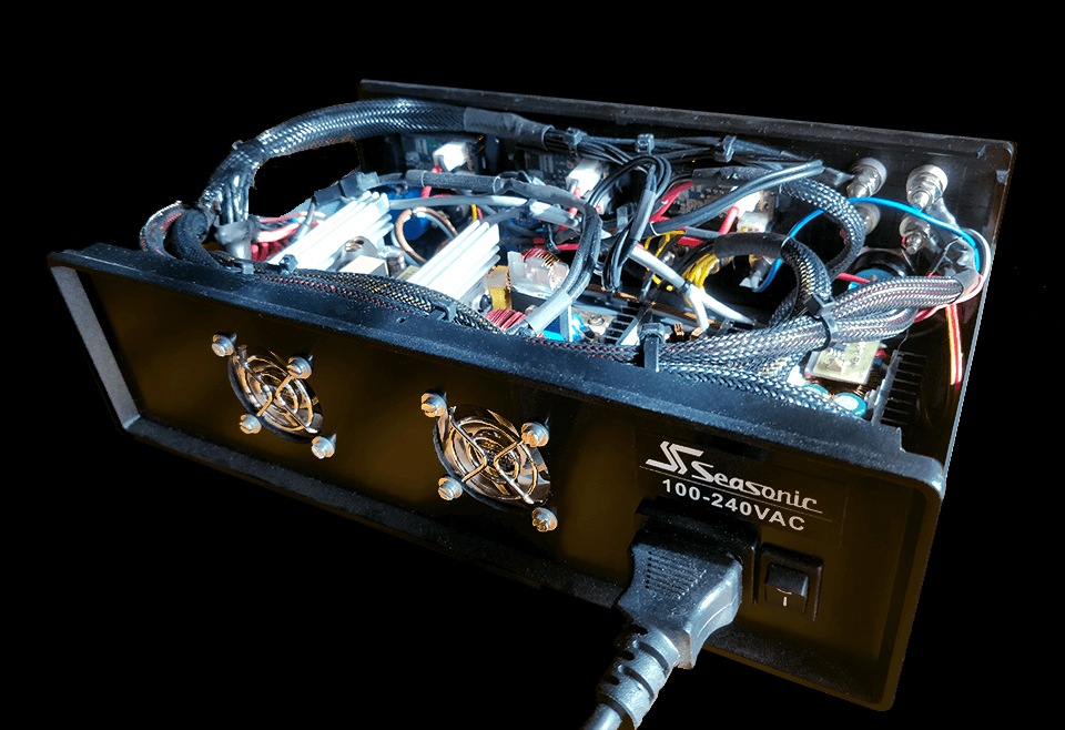
To create this power supply, I used an ATX PC power supply, model S12II 430W from Seasonic (this model is no longer available for sale, but any other equivalent model is of course usable, you’ll just have to adapt the components to the characteristics of the ATX power supply chosen). I used this PSU for several reasons: its silence, its efficiency of over 85% (80PLUS® Bronze), the reliability of its components and its regulation quality. It’s better to use a quality power supply than to get one from an old PC lying around in your garage or from the local garbage dump. The Heden brand, for example, is very common in towers bought in supermarkets, and are very low-end Chinese ATX blocks at less than twenty Euros (!). Why not use this kind of ATX power supply? For a number of reasons: the poor quality of the electronic components, the presence of lead in the soldering, even though this has been banned in Europe since 2011 (RoHS), the real risk of fire, as these power supplies are equipped (or not) with virtually ineffective safety systems, the power ratings shown on the label are often far-fetched (600 W indicated, when the power supply actually delivers only 250 W, for example), disastrous regulation, which may harm your equipment, and significant electromagnetic radiation. For those interested, here’s a very instructive article on PC power supplies published in 2008 on the Canard PC website. This applies not only to those who want to build their own PCs, but also to do-it-yourself enthusiasts who want to salvage a power supply unit and build themselves a laboratory power supply worthy of the name. It’s a generally neglected component, but one whose quality really needs to be taken seriously, especially in computing, where components are very sensitive to voltage fluctuations and parasites.
Materials required
- 1x ATX power supply unit, 430 W or more – e.g. be quiet! System Power 10, 450 W – Amazon (€60)
- 1x 280x170x80 ventilated steel case with plastic front and rear panels – Aliexpress (€30)
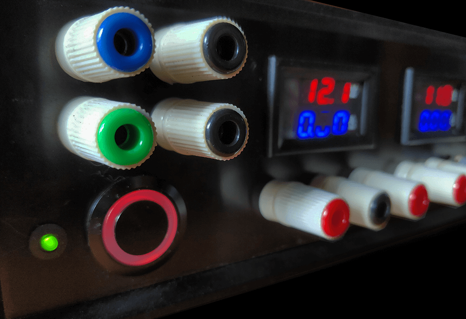
- 3x mini Volt/Ampere displays, DC 0-100 V, 10 A – Aliexpress (10 €)
- 1x Step Down XL4016 280 W DC 300 W DC-DC (adjustable voltage step-down from 0.8 to 12 V) – Aliexpress (3 €)
- 1x Step Up OSKJ 150 W DC 150 W DC-DC (adjustable voltage breeder module from 12 to 35 V – Aliexpress (3 €)
- 2x precision multi-turn potentiometers, 10 K – Aliexpress (3 €)
- 2x plastic buttons (3 €)
- 1x illuminated pushbutton switch 12 V 6 pins diam. 22 (integrated LED) – Aliexpress (1.5 €)
- 3x fuse holders diam. 5 mm for chassis (15 €)
- 3 glass fuses diam. 5 mm of 6.3 A, 10 A and 20A (2 €)
- 1x switch with IEC320 plug – Amazon (10 €)
- 2x ultra-quiet fans (Noctua NF-A4x10, diam. 40 mm, 12 V) – Amazon (€20)
- Female test terminals, M5 type (4 red, 5 black, 1 blue, 1 green) – Aliexpress (10 €)
- Nylon spacers, a few M3 screws + washers + nuts
- Multicore copper cable, diam. 0.25 mm² in various colors (red, yellow, black, green, violet, orange, gray), heat-shrink tubing, various tools (cutting pliers, screwdriver and soldering iron).
- Patience!
You can, of course, use threads of the same color, but watch out for tangles, because there really are a lot of threads!
Schematic diagram
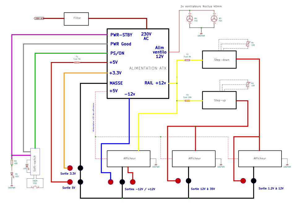
This is a schematic diagram, not a complete electronic circuit diagram (I don’t have the time to make one, nor do I need one). The schematic diagram allows you to understand the entire assembly and to assemble the various components without too much difficulty. The two 40 mm fans are to be connected in place of the large ATX block fan, which will be removed, so that the block’s internal control system can activate or deactivate the fans. Please note that there are many different wires and connections. The use of coloured wires greatly simplifies assembly. As for the cross-section of the wires, you’ll need to do a little calculating, depending on the ATX block you’re using, to avoid overheating the conductors.
Conductor cross-section :
S = ρ x L x I / PT where ρ (copper resistivity) = 1.75 10-8 Ωm or 0.0175
- S = copper conductor cross-section in mm2
- L = conductor length in meters
- I = current expressed in Amperes
- PT = accepted voltage loss at the cables expressed in Volts and which, by convention, is between 2.5% and 5% of the nominal voltage without ever exceeding this value.
That is, for 12V at 10A with a minimum loss of 2.5% (PT = 12 x 2.5%) and a maximum of 5% (PT = 12 x 5%).
Smax = 0.0175 x 0.5 x 10 / (12 x 2.5%)
Smax = 0.0875 /0.3
Smax = 0.29mm²
Smin = 0.0175 x 0.5 x 10 / (12 x 5%)
Smin = 0.0875 x 0.6
Smin = 0.15mm²
i.e. a Smoy of 0.22mm².
That is, for 35V at 8A (the maximum delivered by the circuit), with a minimum loss of 2.5% (PT = 35 x 2.5%) and a maximum of 5% (PT = 35 x 5%).
Smax = 0.0175 x 0.5 x 8 / (35 x 2.5%)
Smax = 0.07 /0.875
Smax = 0.08mm² (0.0175 x 0.5 x 8 / (35 x 2.5%)
Smin = 0.0175 x 0.5 x 8 / (35 x 5%)
Smin = 0.07 /1.75
Smin = 0.04mm²
i.e. a Smoy of 0.06mm².
To avoid having to deal with different cross-sections, we’ll choose the maximum cross-section for the entire assembly, i.e. 0.25mm² (standard cross-section of commercially available cable).
ATX power supply color matching
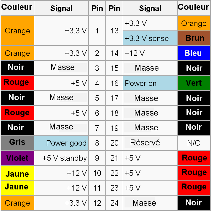
We’ll use the 12-volt rail, i.e. the yellow wires (there are two 12-volt rails on the Seasonic: Rail 1, which can deliver up to 17A, and Rail 2, which also delivers 17A). So we’ll divide the loads between rail 1 and rail 2, the -12 Volts (blue wire), the +5 V for the 5 Volts output and display power supply (red wires), the +3.3 Volts (orange wires), the green PWR-ON wire for starting the power supply via the push-button (see the Soft-switch module below), the violet PWR-STBY +5 V permanent wire to supply the Soft-switch module and the LED indicating that the power supply is connected to the mains, the grey PWR-Good wire to supply the LED incorporated in the push-button indicating that the power supply is live, and finally the various black wires for the different grounds distributed throughout the case.
Digital displays
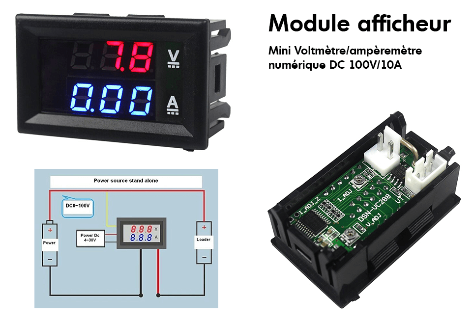
The displays are connected to the rest of the circuit in the same way as if you wanted to connect a voltmeter (in parallel) to measure voltage and an ammeter (in series) to measure current. There are two wires to be connected in parallel to read the output voltage, and two other wires to be connected in series with the output to measure the current. Some modules have a common wire, as on a multimeter, which has a common reference ground. These modules give an idea of the output voltage and the current drawn. They are not measuring instruments! Accuracy is not excellent (around +/- 300 mV and +/- 50 mA), but it’s good enough. For greater accuracy, you can connect your multimeter to one of the outputs for comparison.
Step-up / step-down
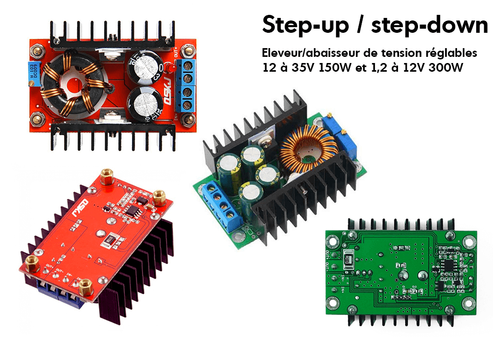
Step-down – XL4016 280W DC
This 240 V DC/DC 5 V to 40 V to 1.25 V to 35 V voltage converter/booster module enables you to reduce an input voltage of 40 V (max) and set the output between 1.25 V and 35 V. Input voltage must be higher than output voltage. This module also features a constant current (CC) adjustment circuit.
The converter/sink design is based on XLSEMI’s XL4016 180 kHz DC/DC converter chip.
In our case, the input voltage is 12 V (ATX rail 1, 12 V), so we can lower and vary the voltage from 1.25 V to 12 V.
Step-up – OSKJ 150W DC
This module is a 150 W, 10-32 V input to 12-35 V output DC/DC voltage converter. It enables you to increase the input voltage from 10V minimum to an adjustable output of 12 V to 35 V. The output voltage will be higher than the input voltage.
The boost converter design is based on the Texas Instrument UC3844 controller chip in PWM current mode.
In our case, the input voltage is 12 V (ATX rail 2, 12 V), so we can boost the output voltage from 12 V to 35 V.
Implementation of the elements
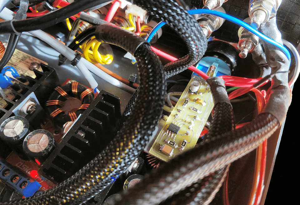
Space is limited. It’s a bit messy, but everything fits perfectly in the 280x170x90 mm case. Depending on the power supply used, the height may vary slightly, so adapt according to the ATX power supply chosen. We can see the three displays (white sockets at the top), the power supply and its radiators on the left, the two Step-up and Step-down modules on the right. The mains filter module removed from the ATX power supply at the bottom left. You just have to make sure that the air circulates as well as possible (the two fans are placed at the back, one at the level of the two aluminium radiators of the power supply and the second in the centre of the case). The Soft-switch module (see below) is soldered directly onto the power button, at the top right.
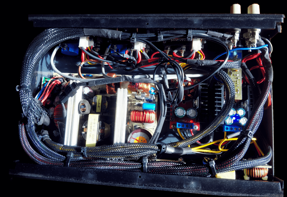
In the photo, you can’t see the rear fuse holders, as they were added later.
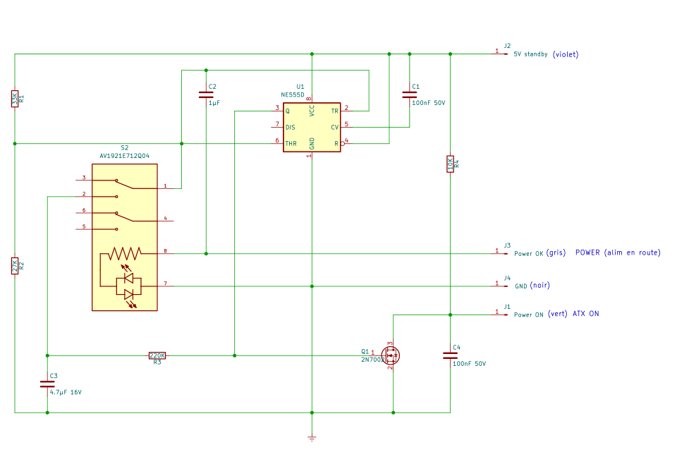
Soft-switch module
A momentary switch that locks? Like on PCs, such a feature is possible. It would be tempting to use a switch that would permanently switch the green PS_ON wire of the ATX block to ground, but in the event of a problem (short circuit) the power supply would not stop! We can imagine the rest… I found different diagrams* on the Internet that I modified a little so that the assembly takes up as little space as possible in a case that is already quite cluttered. The Soft-switch module is soldered directly onto the push button switch. Connected to an ATX power supply, it allows the power supply to be activated simply by pressing a button. If unfortunately a short circuit occurs on one of the power supply outputs, the Soft-switch module instantly cuts off the power supply.
*Links to sources : instructables.com, smallbulb.net and sound-au.com
Note: When starting up for the first time, connect the power supply to the mains. If it starts up immediately without pressing the button, you will need to increase the C1 value.
List of components :
- U1 : NE555D
- R1 : 33KΩ
- R2 : 27KΩ
- R3 : 10KΩ
- C1 C4 : 100nF 50V
- C2 : 1µF 16V
- C3 : 4.7µF 16V
- Q1 : 2N7002
*The SMD components are 1812 type (3.02mm x 2.0mm)
3D view, diagram and PCB made under Kicad
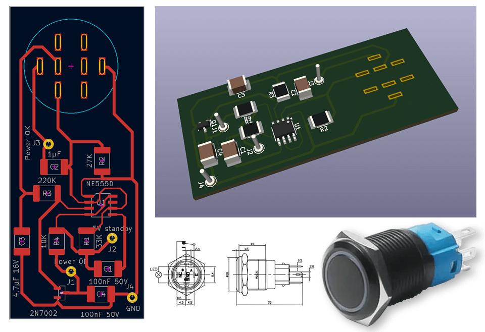
The original version was somewhat different (pictured). The board measures 65mm x 28mm and now only has SMD components.
Cutting and drilling the case
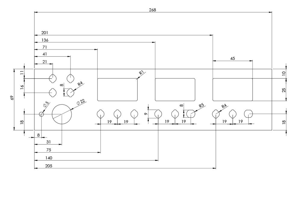
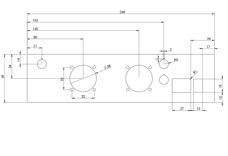
Trace made using FrontDesigner software (available for Windows, Mac and Linux). You can download the software which is free in order to use the file that I put for download below as a cutting template. You can also have the front face engraved directly on the Shaeffer AG website. In 2 mm black anodized aluminum, white screen printing, the final cost (drilling, screen printing, cutting, shipping) is around €70. The rendering is really professional.
The PDF file for download contains the dimensions of the drillings and cutouts in order to be able to make the front and rear panels. The dimensions of course correspond to the case in the description, i.e. 280x170x90 mm (the front and rear panels are 268 mm x 69 mm in 2 mm thickness)
That’s it, that’s it for the lab power supply. Now: Do It Yourself!