
If you own a 27″ iMac model A1312 mid-2011 (EMC 2429) with an LG LCD panel reference LM270WQ1(SD)(E3), with a Chinese module sold on Aliexpress and a few additional components, you can transform your old iMac into a magnificent 2K monitor that will enable you to display a 2560×1440 image at 60HZ.
The Chinese module can be found on Aliexpresse for 25€ (choose ref. LM270WQ1-SDA1 specific to this iMac model). It has its own separate inverter module (circuit managing the panel’s LED backlighting), but the latter doesn’t provide the same brightness as the original iMac. That’s why I’m proposing in this tutorial that you adapt this set-up using the iMac’s original inverter and power supply. To use the original inverter, you need to add an Arduino Nano module to the assembly. With a few lines of code, the Arduino converts the Chinese module’s brightness control signal into a PWM signal that can be understood by the iMac’s original inverter. We can therefore adjust the screen brightness directly from the Chinese module’s control board.
Materials required:
- A 27″ iMac with LCD panel ref. LM270WQ1
- A control module adapted to this tile, ref. LRX_1H1DP1USB55T_V2.0
- iMac power supply ref: PA-23-11-02A
- iMac inverter module ref: V267-604
- The two original iMac speakers
- Two bass/treble filters for iMac speakers
- 2 Micro JST 4-pin female connectors, pre-wired (Amazon)
- An Arduino Nano module (from the Arduino store – watch out for Chinese copies!)
- A computer (Mac or PC) and a USB/USB-C cable for programming the Arduino
- A soldering iron, some solder
- A few coloured flexible wires with a cross-section of 0.25mm².
- Heat-shrink tubing in various diameters
- Paper tape and transparent tape
- Basic tools (pliers, Phillips screwdrivers, Torx T6, T8, T10 screwdrivers, etc.)
iMac components
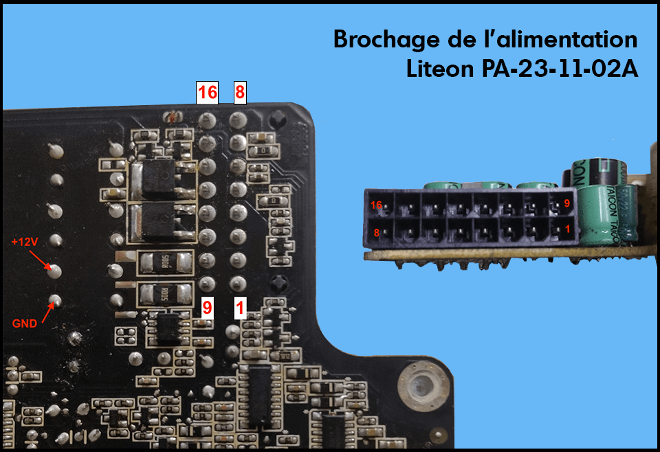
Power supply iMac 27″ mid-2011 A1312 – EMC 2429
Ref.: Liteon PA-23-11-02A
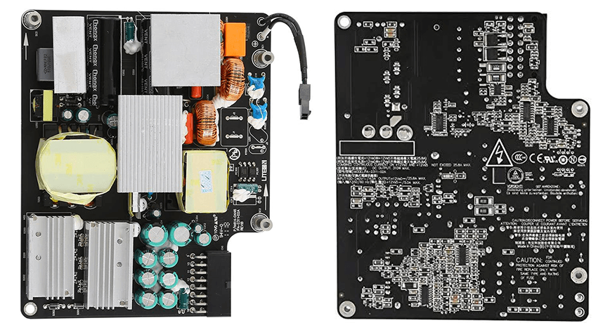
Power supply pinout
| 16: GND (inverter ground) | 8 : GND (inverter ground) |
| 15: backlight 12v (12V inverter power supply) | 7: GND (ground) |
| 14: backlight 12v (power supply 12V inverter) | 6: PS_ON (power on – ground signal) |
| 13: PP12V_S0_PS (12V backplane power supply) | 5: GND (ground) |
| 12: PP12V_S0_PS (12V power supply – backplane) | 4: PP12V_G3H_ACDC (12V permanent) |
| 11: PP12V_S0_PS (12V backplane power supply) | 3: I2C_GND (ground) |
| 10: SMB_ACDC_SDA_RC 5 (3.3V motherboard) | 2: SMB_ACDC_SCL_RC (3.3V motherboard) |
| 9: GND (ground) | 1: GND (ground) |
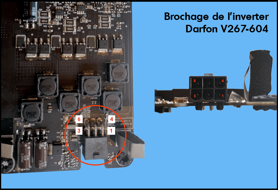
Inverter iMac 27″ mid-2011 A1312 – EMC 2429
Ref. number: Darfon V267-604
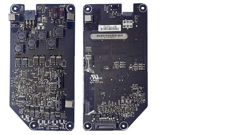
Inverter pinout
| 6: GND (inverter ground) |
| 5 : 12v (12V inverter power supply) |
| 4: GND (inverter ground) |
| 3 : PWM (brightness control) |
| 2: 12V (12V inverter supply) |
| 1 : BL_ON (inverter start => +5V signal) |
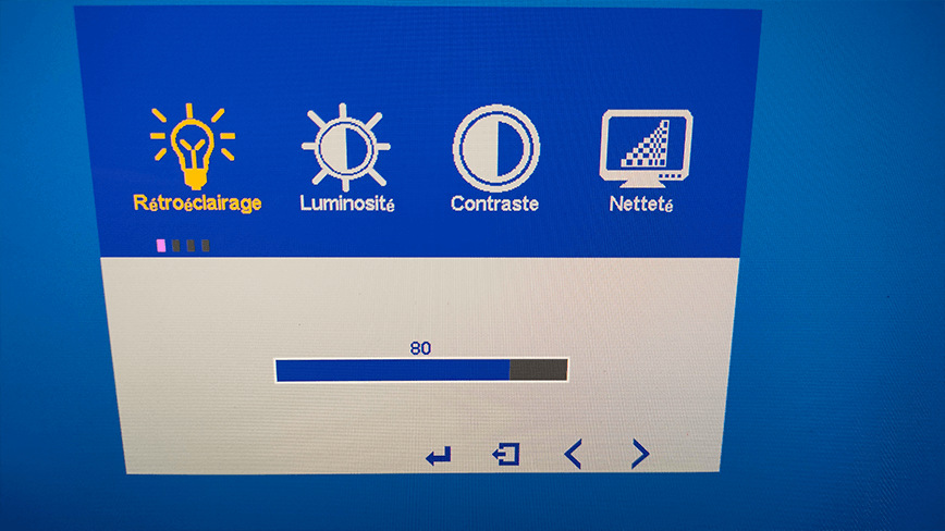
Brightness control
The iMac’s screen backlighting system uses pulse-width modulation (PWM*) to control backlight intensity. A PWM control signal is generated in the iMac’s motherboard/video card circuitry and routed to the PWM input of the inverter board that manages the LCD panel’s backlighting. The PWM frequency generated by the iMac is 13 KHz and the pulse height is 3.25 V. The duty cycle therefore varies from 0 to 100% to adjust the backlight intensity from minimum to maximum power.
Important: To switch on the backlight, +5V must be supplied to pin 1 (BL_ON) of the inverter.
*Note: PWM stands for Pulse Width Modulation. The principle of PWM is to reduce the average power output of a digital output (0 or 1) by modulating the signal pulses. The aim is to create a pseudo-analog output that can take 256 values (0 to 255). PWM is used, for example, to control LED brightness.
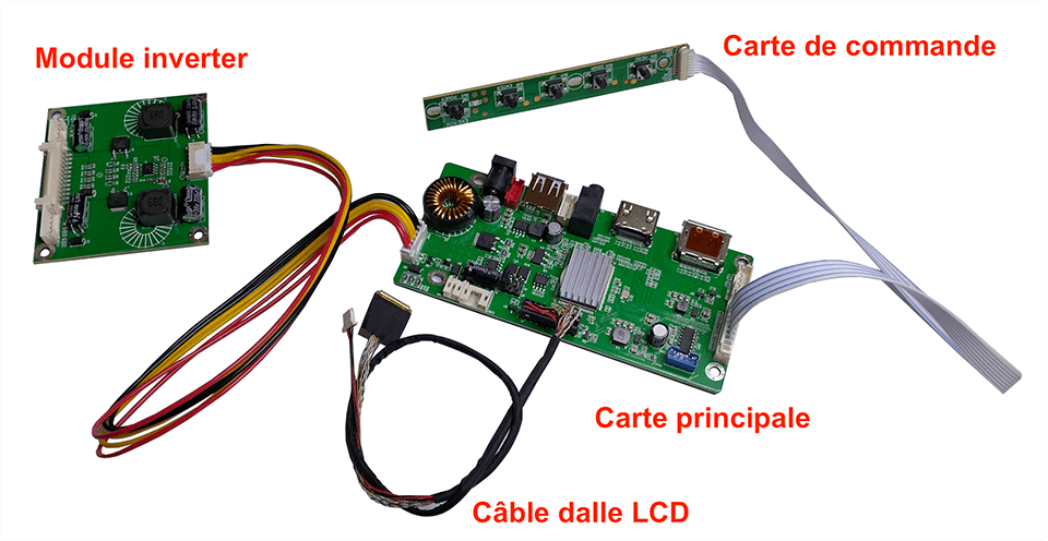
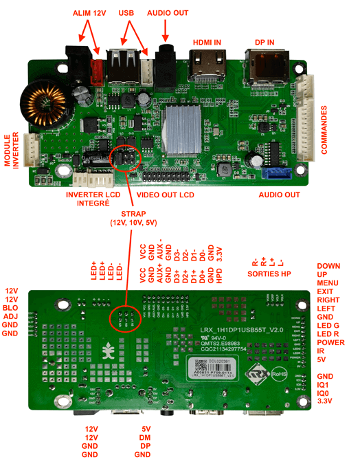
The Chinese control module
Reference: LRX_1H1DP1USB55T_V2.0
Connector pin-outs :
Connector description
Power supply 12V/1A:
- 1x Power Jack diam. 4.75/2 (positive pole in center)
or - 1x Micro JST 4-pin connector (red)
USB:
- 1x USB 2.0 port
or - 1x Micro JST 4-pin connector (white)
Audio IN (stereo) :
- 1x jack 3.5 female, stereo
Audio OUT (stereo) :
- 1x Micro JST 4-pin connector (blue)
Video:
- 1x HDMI female SMD connector
and/or - 1x Displayport female SMD socket
Outputs to inverter module:
- 1x Micro JST 6-pin connector (white)
or - 1x Micro JST 4-pin connector (white) => not used
Strap (choice of supply voltage)
- 3 positions: 12V, 10V or 5V (12 volts in this configuration)
Video OUT LCD:
- 1 Strip 2×10 pins connector (cable with ZIF connectors and JST vertical sync connector supplied)
Ordering:
- 1 Micro JST 12-pin connector (white) => only 8 pins are used for control (Power, Menu, Down, Up, Enter)
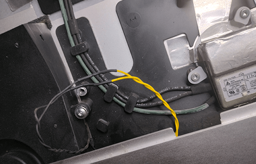
Power supply
Power is supplied to the module by connecting pin 4 (PP12V_G3H_ACDC) of the PSU ( Power Supply Unit), which delivers a constant 12 Volts at 5 Amps. You can solder a wire directly to the PSU, but the cleanest solution is to use the iMac’s original cable connecting the PSU to the inverter and to the motherboard, removed from the chassis (!). Simply connect an iMac-specific 2×7-pin female Molex plug to the end of the cable and wire pin 1, 2 or 3 for ground and pin 11 for permanent +12V.
Note: permanent 12 volts are present as soon as the iMac is connected to the mains via the IEC C13 socket.
Molex connector pinout
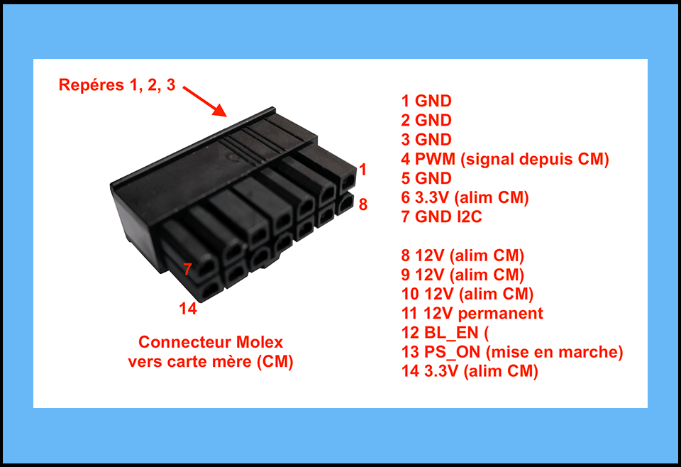
MOLEX female connector :
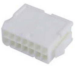
Number: 39012146
Series: 5559
Part Number : 5559-14P-210
Product family : Mini-Fit Family Power Connectors
Male crimp pin: Molex Mini-fit, ref.: 39000041
Please note Please note: the pin-outs of the various iMac boards (PSU, Inverter, MOLEX motherboard) vary according to iMac model, even for visually identical 27″ models. Everything explained here applies ONLY 27″ iMac A1312 mid-2011 (EMC 2429). There are no Apple standards, and each model has its own specific characteristics.
There are 10 different iMac 27″ versions!For other iMac models, you’ll need to adapt the different pin-outs if necessary.
Using the iMac inverter
The power delivered by the Chinese controller’s inverter is not sufficient to obtain the iMac’s original brightness. In order to manage the backlighting of the LCD panel using the original inverter (Model V267-604), we need to convert the analog control signal from the Chinese board into a PWM signal that can be understood by the Apple inverter.
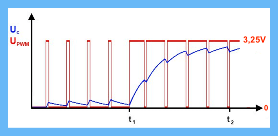
UC = analog signal generated by the control board
Upwm = digital PWM signal generated by the iMac motherboard
To replace the PWM signal of the motherboard, we will use an Arduino Nano powered by 5V (consumption 20mA max) to convert the analog signal (0-5V) of the Chinese controller into an adequate PWM signal (rectangular signal of 3.25V, 13kHz) understandable by the inverter of the iMac. It is therefore a system of substitution for the PWM signal normally generated by the motherboard of the iMac. It is now possible with this assembly to use the native brightness control buttons of the Chinese controller to vary the brightness of the screen via the original inverter of the iMac and thus obtain a brightness worthy of an iMac.
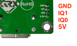
Note: The 5V power supply of the Arduino will be taken from the connector located on the Chinese controller board: Micro JST connector, pin 1 (5V) and pin 4 (GND). It is indicated 3.3V on the printed circuit but the board actually delivers 5V (?) only when the board is activated, which is important because the other 5V voltages on the board (USB port for example) are present permanently. The low 20mA consumed by the Arduino are not likely to destroy the power supply circuit of the Chinese board which should largely deliver the necessary current.
The Arduino Nano board
Arduino/inverter module connections :
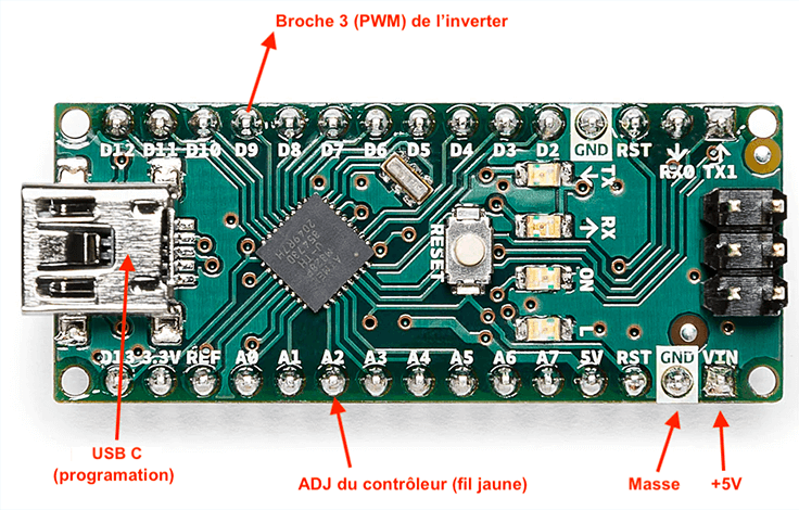
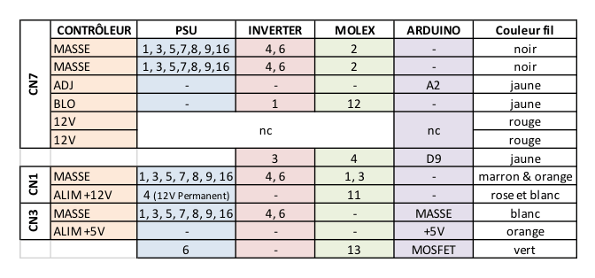
- BLO wire (yellow +5V wire) from Chinese controller: connected to pin 1 (BL_ON) of inverter or pin 12 (BL_EN) of Molex connector
- Chinese controller ADJ pin: connected to Arduino A2 input pin
- Arduino output pin D9: connected to pin 3 (PWM) of the Apple inverter or to pin 4 (PWM) of the Molex connector
See the summary table of the different connections.
Arduino/module power supply connections :
- Arduino GND pin: Connected to pin 4 (GND) of the controller
- VIN pin on the Arduino: connected to pin 1 (+5V ) on the controller
See the summary table of the different connections.
Modified Arduino program (created by Frédéric R on iFixit @fredericro66259)
Download the Integrated Development Environment (IDE) for Arduino from the Arduino website (available for Windows, Mac, and Linux): https://www.arduino.cc/en/software
Install it on your computer.
Connecting the Arduino board to the computer:
Connect your board to your computer using your USB/micro USB cable.
Your Arduino is powered from this USB connection in 5V and can now be programmed.
Configuration :
To start using your board, select the “Arduino Nano” entry in the Tools>Board type. Then select the serial port in Tools>Port. To find out which port your Arduino is connected to, you can disconnect your board and reopen the menu. The entry that disappears should be your Arduino Nano (probably COM3 or higher). Reconnect your Arduino board and select the serial port, which should now have reappeared. You’ve just configured your Arduino board!
Installing the Arduino TimerOne library :
The PWM program requires this library. You can download and install the Arduino TimerOne library manually from GitHub, or install it in the Arduino IDE itself. Simply open the library manager Tools > Manage libraries > Search TimerOne. Then click on Install and let the installation complete.
Write the code and program the Arduino :
- In the IDE, click on File>New
Copy/paste the code below into the code editor. - Save the code on your computer as a backup File>Save as… (name it as you like) then click on Save.
- Then click on the button with the green tick in the top left-hand corner of the IDE window. This button verifies your code, i.e. checks for errors, then compiles it ready for download to your Arduino board.
- If the compilation step is successful, your IDE will display a message in the output window at the bottom telling you that your code has completed compilation.
- The LED on your Arduino should now be blinking.
- That’s it, you can remove the USB/micro USB cable.
The code*
#include <TimerOne.h>

#define PWM_PIN 9
#define POT_PIN A2
#define FREQUENCY 13000 // Frequency in Hz for PWM output
#define VCC 5.0 // Arduino supply voltage (5V)
#define MAX_OUTPUT_VOLTAGE 3.25 // Maximum PWM output voltage of 3.25V

void setup() {
  pinMode(PWM_PIN, OUTPUT);
  pinMode(POT_PIN, INPUT);

  // Configure TimerOne for a frequency of 13 kHz
  Timer1.initialize(1000000 / FREQUENCY); // Period in microseconds
}
void loop() {
  // Read the value of the input signal (0 to 1023)
  int inputValue = analogRead(POT_PIN);

  // Convert the input reading into a PWM value (0 to 1023), with a 65% ceiling for 3.25V
  float dutyCycle = map(inputValue, 0, 1023, 0, 100) / 100.0; // Convert to percentage

  // Ensure that the duty cycle does not exceed that corresponding to 3.25V
  dutyCycle = min(dutyCycle, MAX_OUTPUT_VOLTAGE / VCC);
  int pwmValue = (int)(dutyCycle * 1023.0);

  // Update PWM duty cycle according to input voltage
  Timer1.pwm(PWM_PIN, pwmValue);

  // Short pause to avoid overloading CPU
  delayMicroseconds(77); // Check input every 13kHz
}
Note: * code modified by myself from the original.
Code explaination
First block :
#include <TimerOne.h>
Loads the TimerOne library and defines the pins used and various variables.
The Arduino TimerOne library is a community-contributed library that allows users to configure and use the Timer1 (16-bit) to generate and manage periodic interrupts, and also to generate PWM signals with controllable frequency and duty cycle. PWM signals are managed in the code with the Timer1 instruction, only on pins 9 and/or 10 (Arduino Nano).
Other blocks:
Explanations:
- Alimentation et Fréquence :
- The Arduino is powered by 5V, but we need to limit our PWM output to 3.25V maximum. The output frequency is set to 13 kHz.
- Conversion de l’Entrée :
- The reading from pin A2 is 0 to 1023, representing an input voltage of 0 to 5 volts. However, we need to convert this input to a duty cycle that does not exceed 65% to meet our output voltage limit.
- Mappage et Limitation :
- The map() function is used to convert the input reading (0-1023) into a percentage from 0 to 100. This percentage is then converted into a PWM value, but limited so as not to exceed the voltage of 3.25 volts (65% of the total duty cycle).
- Mise à Jour du PWM :
- The duty cycle is updated in real time based on the input voltage, always respecting the maximum voltage constraint.
Using delay() or delayMicroseconds() in this context can potentially introduce flicker into the LCD backlight, especially if the input state check period (controlled by delay()) is not optimally synchronized with the output PWM frequency. Here’s why:
- Refresh Inconsistency: If the frequency at which you update the PWM signal based on the input is not in phase or synchronized with the frequency of the PWM itself, you may get changes in brightness perceived as flicker.
- Human Refresh Rate: Human eyes are particularly sensitive to brightness changes in the 10-60 Hz range. If the interval between backlight brightness updates falls into this range or creates beats with the PWM refresh rate, this may be perceived as flickering.
- 13kHz PWM: Using a PWM frequency of 13kHz is usually high enough that flicker is not noticeable to most people under normal conditions. However, if the PWM update based on the input state is done too slowly or at a rate that interferes with this frequency, the problem may still occur.
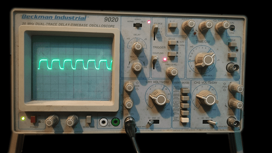
PWM Theory: Test & Simulation under Proteus Software (v.8.13)
Proteus software is an electronic circuit simulator. A demo version can be downloaded from their website. The free version has no time limit for PCB layout evaluation but 14 days for microcontroller (Arduino) simulation.
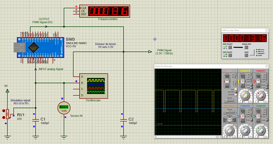
To simulate the command (ADJ pin of the Chinese module) we vary the voltage from 0 to 5V using RV1 on the analog input (pin 2) of the Arduino Nano. The PWM signal generated by the Arduino on pin 9 varies proportionally to the simulated signal of the Chinese controller card. This is the pin that will have to be connected to pin 3 (PWM) of the iMac inverter.
The 1nF capacitors C1 and C2 are used for several things:
- Noise Filtering: The capacitor can act as a low-pass filter, attenuating high frequencies or electrical noise present on the transistor’s output line. This is particularly useful for minimizing electromagnetic interference (EMI) that could affect the operation of the circuit or adjacent circuits.
- Voltage stabilization: If the transistor is used to switch a load, the capacitor can help stabilize the output voltage by absorbing voltage spikes that may occur during rapid transitions (such as when switching a coil or motor). This can reduce surges that could damage the transistor or other components.
- Flicker reduction in PWM applications.
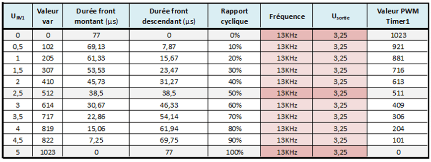
The frequency measured is 1316HZ on the frequency meter, or ≈ 13KHz (frequency requested by the iMac inverter). This frequency is confirmed by calculating the values measured on the Arduino and the resulting duty cycle (see table).
Note: It’s the duty cycle that varies the luminous intensity of the LCD panel, not the frequency and/or voltage.
Frequency and duty cycle
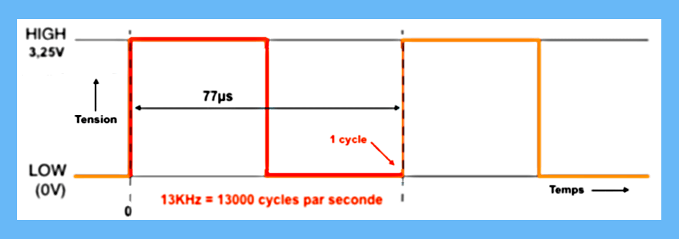
1 cycle corresponds to the passage from a high state (3.25v) to a low state (0V) in a time t.
The frequency being equal to: fHZ = 1/ts
Here, f = 1/77µs = 1/0.00077s = 1299HZ or ≈ 13KHz
Over a cycle, when the ratio between the rising edge (passage from 0 to +3.25V) and the falling edge (passage from +3.25V to 0) are of the same duration, the duty cycle is 50%.
PMW at 50%: The frequency is still 13KHz (77µs) and the duty cycle is 50%. The voltage remains at 3.25V
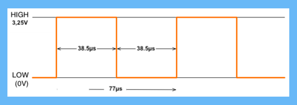
Over a cycle, when the ratio between the rising edge and the falling edge are of different durations, the duty cycle varies:
- If the duration of the rising edge is greater than the duration of the falling edge, the duty cycle is greater than 50%
=> the brightness increases- If the duration of the rising edge is less than the duration of the falling edge, the duty cycle is less than 50%.
=> brightness decreases
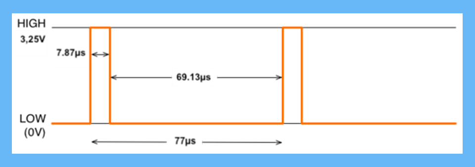
PWM at 10: The frequency is still 13KHz (77µs) and the duty cycle 10%. Voltage remains at 3.25V
ADJ & PWM signals read on oscilloscope :
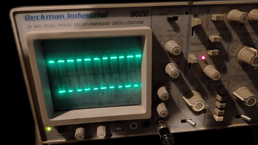
Measured Arduino PWM values:
Power supply start-up
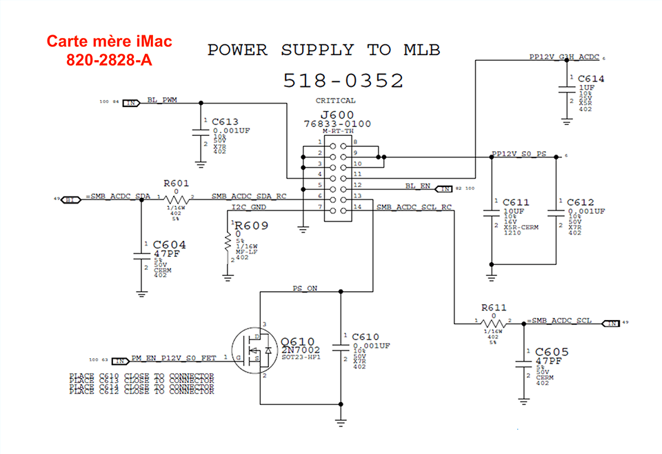
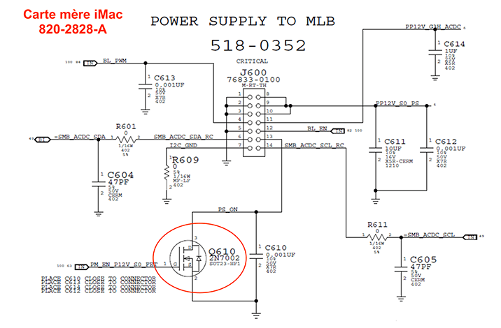
As soon as you connect the iMac to the mains, only permanent 12V is available on pin 4 of the PSU (or pin 11 of the Molex connector on the cable connecting the PSU to the motherboard). In order to start up the PSU completely, enabling it to supply the other voltages and power the inverter, it is necessary to connect pin 6 (PS_ON) of the PSU (or pin 13 of the Molex connector) to ground, but this is not very conventional, as all the elements would then be permanently powered. On the one hand, this would consume energy unnecessarily, and on the other, it wouldn’t be safe, since different voltages would be present all the time. It would be more interesting to use a MOSFET transistor that would act as an “electronic switch”, like the one originally used on the iMac motherboard or on all PC ATX power supplies. The iMac motherboard schematic below shows the SMD MOSFET Q610 (2N7002), which grounds pin 13 of Molex connector J600 when a 12V signal (PM_EN_P12V_SO_FET) from a start-up voltage control sub-circuit on the original motherboard is applied to its G trigger.
Implementation
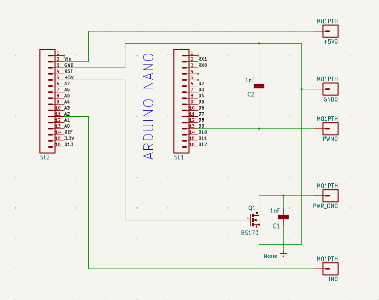
A simple circuit consisting of a BS170 MOSFET transistor (equivalent to the 2N7002 but not SMD) to which a voltage of 5V is applied, with a 1nF capacitor in parallel between its output and ground and that’s it.
Power cycle:
- The screen plug is connected to the mains, the power supply delivers permanent 12V (pin 4: PP12V_G3H_ACDC or pin 11 Molex). The Chinese control card and the monitor are in standby mode.
- These 12V supply the Chinese control module. Pressing the start button starts the control module.
- The 5V now present on the control module’s JST connector (see previous explanation ) is then used to power the Arduino.
- The Arduino in turn starts up and delivers 5V on pin 27, which is connected to our transistor’s trigger. The transistor then grounds pin 6 of the Apple power supply (PS_ON). The iMac’s power supply starts up completely.
- The inverter is then supplied with 12V (pins 14 and 15 of the power supply, 2 and 5 of the inverter). As 5V is already present on pin 1 (BL_ON), the inverter starts up and the LCD panel lights up.
- Pins 11, 12 or 13 of the PSU now provide a new 12V supply to power the fan controller (seefan power supply below) or anything else you’d like to add to the assembly and supply with 12V.
- If the power button is pressed again, the control module goes into standby mode and there is no more 5V on the JST connector, the Arduino is no longer powered, there is no more 5V on the transistor trigger. This then disconnects pin 6 from the PSU ground. The Apple power supply stops, the fans, then the inverter. The monitor is back in standby mode.
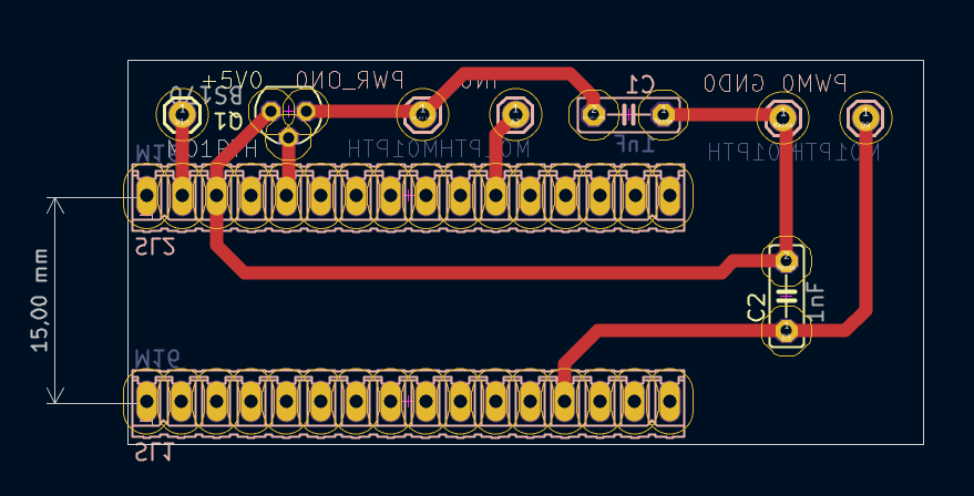
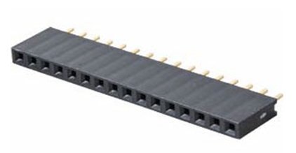
I made a small PCB on which I fixed the Arduino module on two 16-pin female headers (MPE 094-1-016), which makes it easy to remove. The 1nF capacitors C1 and C2 are used for several things:
- Noise filtering : The capacitor can act as a low-pass filter, attenuating high frequencies or electrical noise present on the transistor’s output line.
- Voltage Stabilization: If the transistor is used to switch a load, the capacitor can help stabilize the output voltage by absorbing voltage spikes that might occur during rapid transitions (such as when switching a coil or motor). This can reduce surges that could damage the transistor or other components.
- Flicker reduction in PWM applications.
List of components
C1, C2: 1nF
Q1: BS170 Mosfet Transistor
2x MPE094 1_16 strip
Download the schematic and PCB for Kicad:
Disassembling the iMac
If you’ve never disassembled an iMac, refer to a tutorial on iFixit, for example.
Once the glass and LCD panel have been removed from the iMac, remove the items listed below:
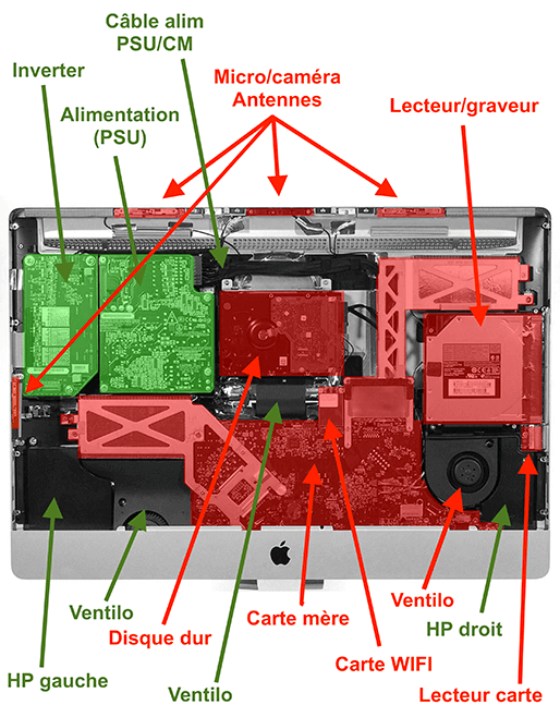
We only keep (in green):
- The inverter
- The power supply unit (PSU
- The inverter/PSU/CM power cable
- The two speakers (left and right)
- The central fan
- The plastic spacers and screws
We remove the glass and the LCD panel (be careful of the cables!)
Then we remove (in red) in order:
- The hard drive
- The WIFI card
- The CD reader/writer
- The RAM
- The infrared receiver (located behind the apple)
- The motherboard and its cables
- The right speaker
- The SD card reader
- The camera and all the antennas (except the round one which is glued to the middle of the chassis)
- The audio connector (2 3.5 jacks) located behind the right speaker in the lower corner of the chassis
- The left fan to be replaced by another Apple fan (see explanations in the fans section)
- The temperature sensor glued to the right fan
LCD panel
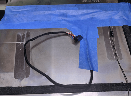
Carefully place the LCD panel upside down on bubble wrap to avoid damaging it.
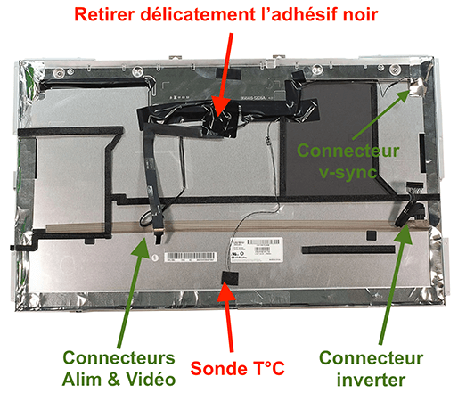
Carefully remove the black adhesive (cut with a scalpel, paying attention to the printed circuit board underneath).
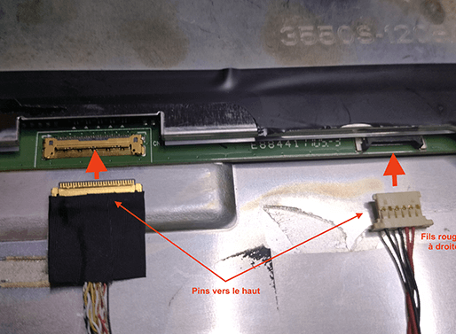
Lift the latch to remove the ZIF cables and the power connector from the panel.
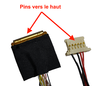
Connect the Chinese module cable to the ZIF connector (pins facing up) and the power connector to the LCD panel, in the same direction as in the photo below. Note: Connectors placed upside down may damage the ZIF connector on the LCD panel.
Note: There is no latch on the ZIF connector of the Chinese board unlike the original Apple cable. Once the connector is inserted, secure it with a small piece of clear tape.
That’s it, set the LCD panel aside for now.
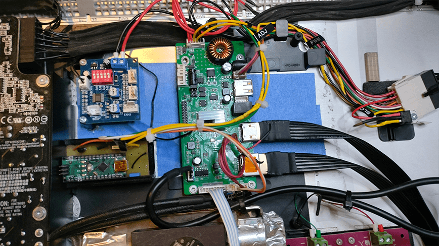
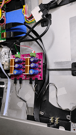
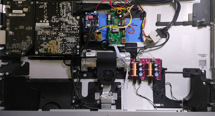
Mounting the Cards to the iMac Chassis
You can fix the cards with spacers glued with two-component glue and screws.
It is better to use colored wires to better find your way around.
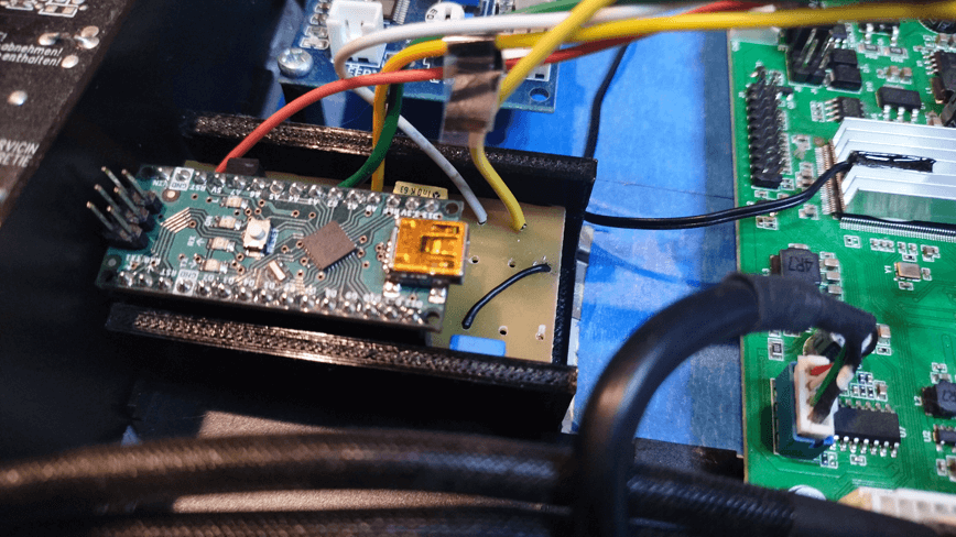
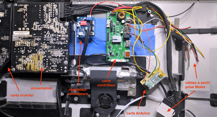
Beware of contact with the iMac chassis, which is made of aluminum and therefore conductive, and which is earthed by the power cord. To be on the safe side, insulate the back of the cards with paper tape, for example (in blue on the photo).
In the photo the wires are not yet crimped and placed in the male Molex socket and the Arduino module is not attached.
Connections of the different cables
Pay attention to the position of the cards in depth, there must be enough space left to be able to replace the LCD panel without it coming into contact with the cards (do not exceed the height of the PSU card) and arrange the cables so as to leave enough space for air to circulate.
Video circuit
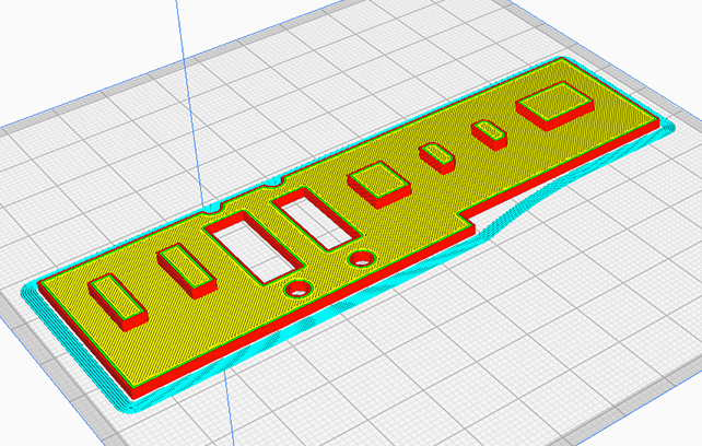
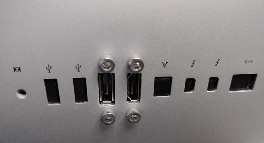
In order not to make a hole behind the iMac to let the HDMI and/or Displayport cable out and especially not to have a cable “hooked” to the monitor, I 3D printed a plate to hide the holes of the old USB ports of the iMac and also to install two video sockets (1x HDMI and 1x Displayport)
Implementation
So, for the more adventurous, the HDMI (and/or Displayport) cable will have to be connected to the controller card and immobilized so that it does not disconnect. It will also be necessary to cut the width of the HDMI (and/or Displayport) socket to the location of the old USB ports, allowing the two connectors to be fixed to the chassis. A 3D printed part will therefore have to be made in order to have a clean hole.
There are ready-made ribbon cables with HDMI and Displayport male sockets and female screw connectors available for around ten Euros on Aliexpress. Different models are available with ribbon cables of varying lengths from 3cm to 3m and straight or angled connectors (to be chosen according to your configuration)

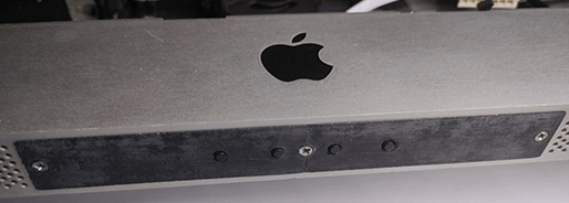
Mounting the module control to the iMac chassis
In order to best integrate the control board of the Chinese module, we will use the access hatch to the RAM memory strips of the iMac.
There are two methods:
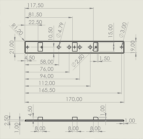
Either it will be enough to drill the grid (hatchet) with 5 holes of diameter 4mm for the buttons and 2 holes of diameter 3mm for the fixing screws (countersink these two holes to accommodate the screw heads). Insert 3 M3 spacers of 4mm in nylon between the board and the hatch which will allow the buttons to be flush and to be sufficiently accessible but discreet enough.

The original screws are kept at the ends for fixing the hatch to the chassis. The middle screw is screwed into the central spacer. Use M3 countersunk screws of length 20mm and two nuts.
Note: You will need to remove the central plastic part (the part where the middle screw is screwed) from the iMac chassis using a small disk and a Dremel, as it interferes with inserting the card into the slot. Also remove the circlip that holds the central screw before installing the control board.
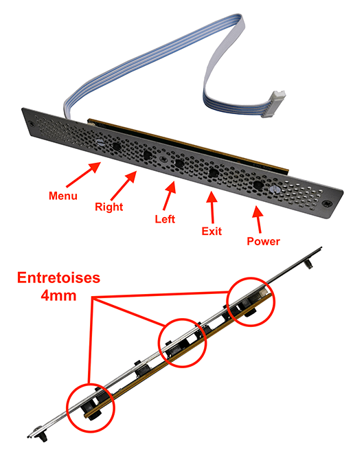
Note: We can also use the iMac’s power button to turn on the display. To do this, we will need to unsolder the Power button from the control board and solder two wires instead that we will connect to the iMac’s button connector. In this case, only make 4 holes of 4mm diameter in the aluminum hatch when drilling.
And the second method:
Option: making a 3D printed hatch
To make it cleaner, I made a 3D printed hatch. It is made of black ABS but it can be made of PLA. The STL file is available for download below. There are only 4 holes for the control buttons because the iMac’s M/A switch is used. You will first need to unsolder the Power button on the control board (the one furthest from the connector) and replace it with two wires that will be connected to the iMac’s start button (photo above)
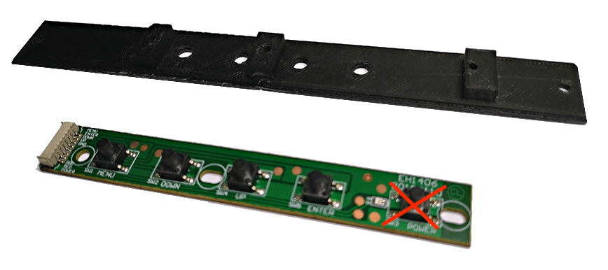
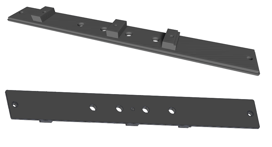
Note: I had to drill a small hole later with a diameter of 3mm just under the LED in order to visualize the operating status of the card. LED off (monitor in standby), green LED (in operation), red LED (no video signal).
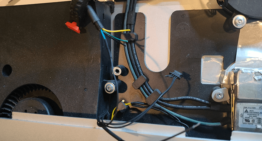
Connecting the fans
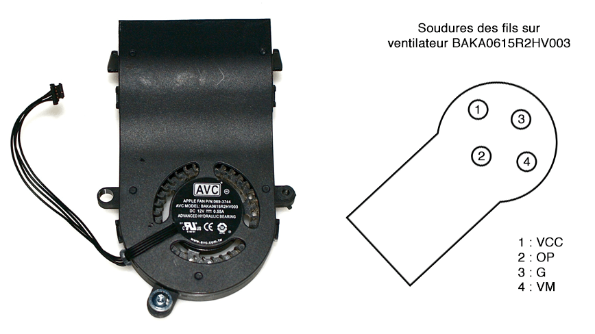
In order to cool the screen, the power supply, the inverter and the controller card, we will keep 2 of the 3 fans of the iMac: the central one for the controller and the left one will have to be replaced because it does not work with the module. To regulate their speeds, a small module found on Amazon allows you to connect three PWM fans (4-wire) manually adjustable using a Dip-switch or controlled by a temperature probe (FAN1 only). It is the latter that we will attach to the processor heatsink of the Chinese controller card (see the module instructions for settings)
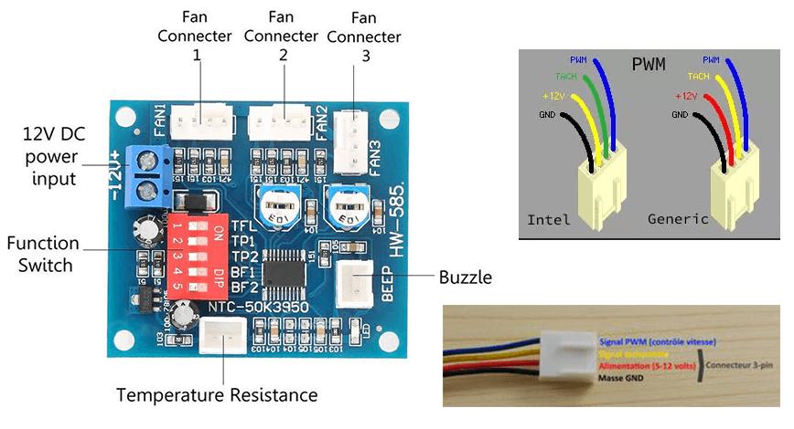
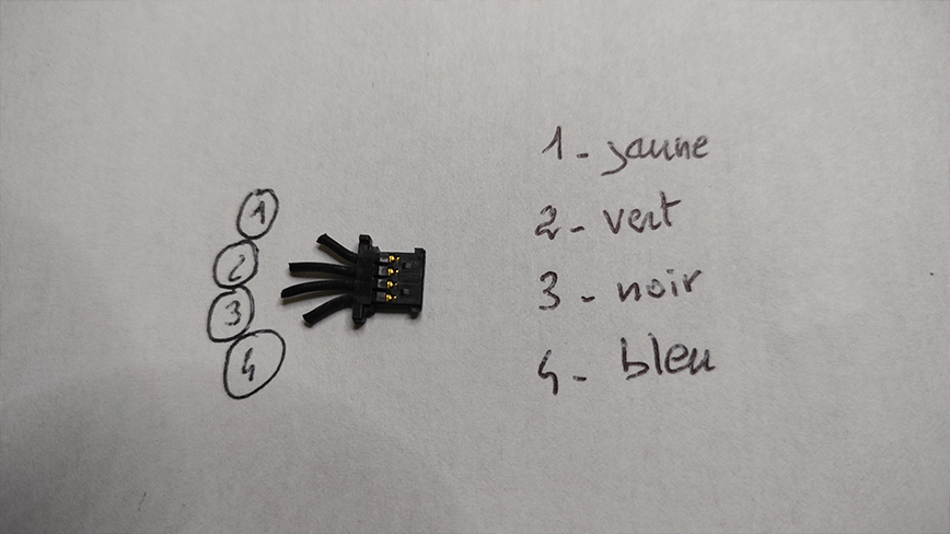
The pinout for Apple fans is as follows:
- +12V (VCC) – corresponds to the yellow/or red wire (VM pin of iMac fans)
- O/P (feedback sens) – corresponds to the green/or yellow wire (OP pin of iMac fans)
- GND (ground) – corresponds to the black wire (G pin of iMac fans)
- VM PWM (command) – corresponds to the blue wire (VCC pin of iMac fans)
For the processor fan (BFB1012MD-HM00), I couldn’t get it to work with the PWM generator. Replaced it with another Apple fan (BAKA0722B2HV002) which has the same pinout as the central fan (BAKA0615R2HV003).
Warning: On Apple fans, the power supply wire and the PWM signal wire must be reversed.
Note: Depending on the connector (Intel or generic) you connect to the speed controller, adapt the color of the wires corresponding to the Apple fan connectors, which have 4 wires… all black (!) as shown in the diagram above.
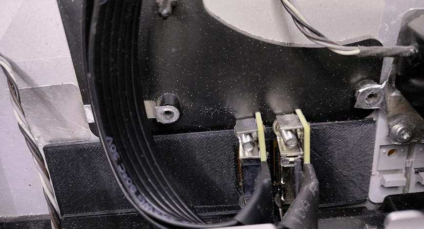
Connecting the speakers
The right and left iMac speakers each have two channels. A woofer for the bass and a tweeter for the treble. This is possible by recovering the stereo audio signal at the output of the Chinese controller card (4-pin Micro JST connector, blue). To do this, it is necessary to insert a filter on each channel in order to distribute the bass/treble frequencies on each of the iMac speakers. There is a filter on Amazon (largely oversized and given for 400W (!) while the iMac speakers are given for 17W!) but since I did not have time to make a miniature filter, I opted for the ready-made option for cheap. In addition, they are sold in pairs. You can design if you wish a double filter of much smaller size, here is the diagram, using miniature wound inductors of similar value (150mH) but in 20 watts which are obviously much smaller and 25V capacitors which are also much smaller:
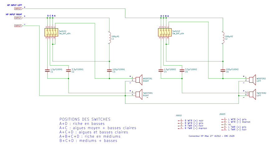
List of module components:
- C1 : 1.5µF 100V
- C2 : 3.3µF 100V
- C3 : 100µF 100V
- L1 : 166µH
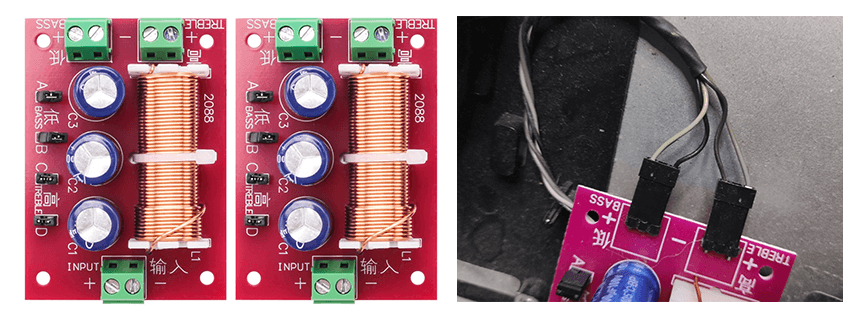
It will be enough to connect the audio outputs of the Chinese controller to the filters:
Vol R- and Vol R+ to the INPUT connector of the filter for the right channel, Vol L- and Vol L+ to the INPUT connector of the filter for the left channel and the iMac speakers to the outputs of the corresponding filters (TREMBLE & BASS). Respect the polarities. In the photo I removed the screw terminals and soldered 4 pins angled at 90° allowing to directly connect the wires of the iMac speakers without cutting them.
iMac Speaker Pinouts:
- Bass +: light gray wire
- Bass -: black wire
- Treble +: dark gray wire
- Treble -: brown wire
Jumpers A, B, C and D on the filters are used to modify frequency distribution and filtering:
A for the lower limit, while B for the upper limit of the bass audio range.
C and D are used to control the treble range. C + D set to OFF: no treble.
Personally, I set them to A+D.
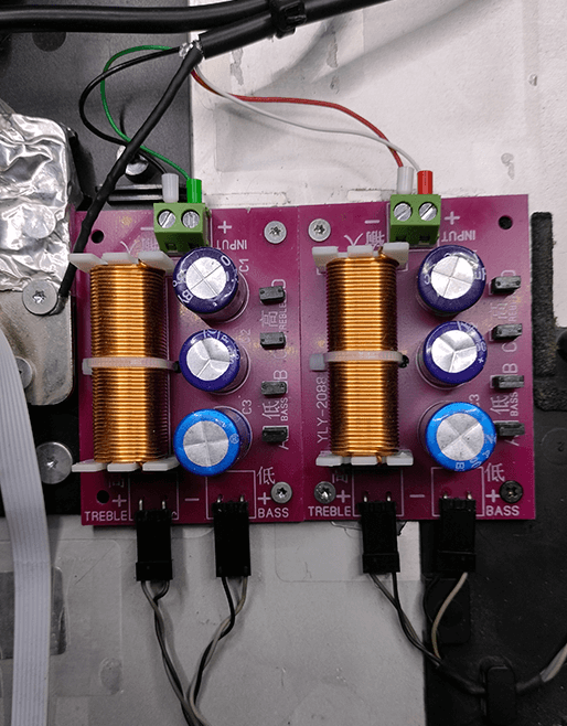
Given the height of the filters, they will be placed in the central part. Also so that they do not touch the aluminum of the chassis, I inserted a 2mm thick plastic plate printed in 3D and which also allows them to be fixed with screws.
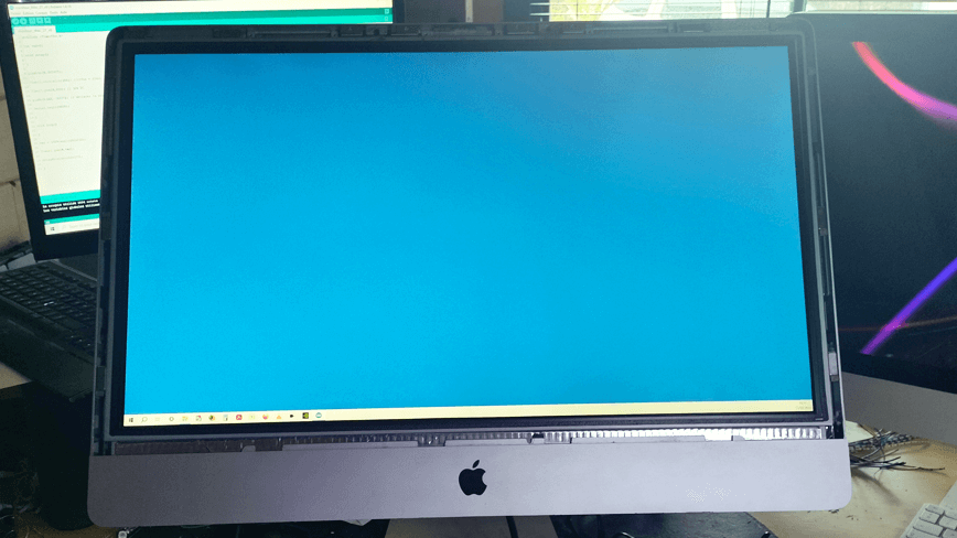
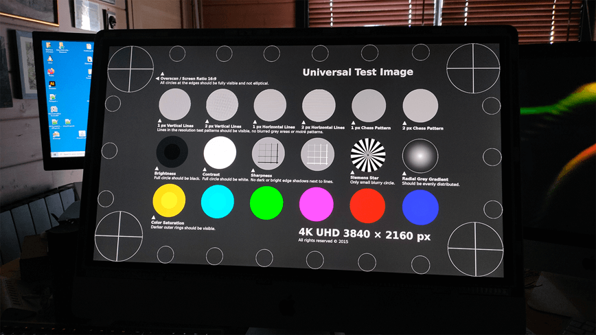
Reassembly of the slab and tests
After months, everything seems to be working. We’ll see with time…
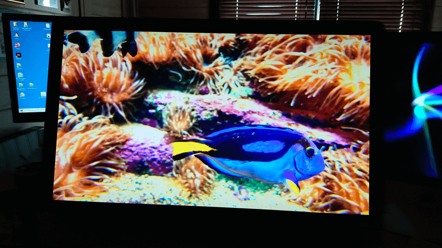
I hope all these explanations will be useful to you. I have searched the web for so much information on this subject and read a lot of things (good and bad) that it seemed necessary to write this article. You can find 27″ iMacs that are broken (motherboard or very often graphics card HS) second-hand and for less than 100€. By investing less than 200€ and spending a lot of time and patience, it is therefore possible to have a beautiful 27-inch screen for your computer.
Good luck.
Thank you so much for your effort, documentation and sharing it with us. I am also experimenting with the same display since month and your documentation brings me a huge step further.
Parabéns pelo tutorial bem explicado, já vou começar a minha modificação.
Obrigado. Desejo-lhe boa sorte em seus empreendimentos. Não hesite em entrar em contato comigo novamente se tiver alguma dúvida.