Installing a TFT screen on a Geeetech A10 (GT2560 V3) is possible!
3.5″ to 7″ color screen, touchscreen, configurable, multilingual. WIFI module (option). Faster heating, possible use of BL Touch, easy calibration
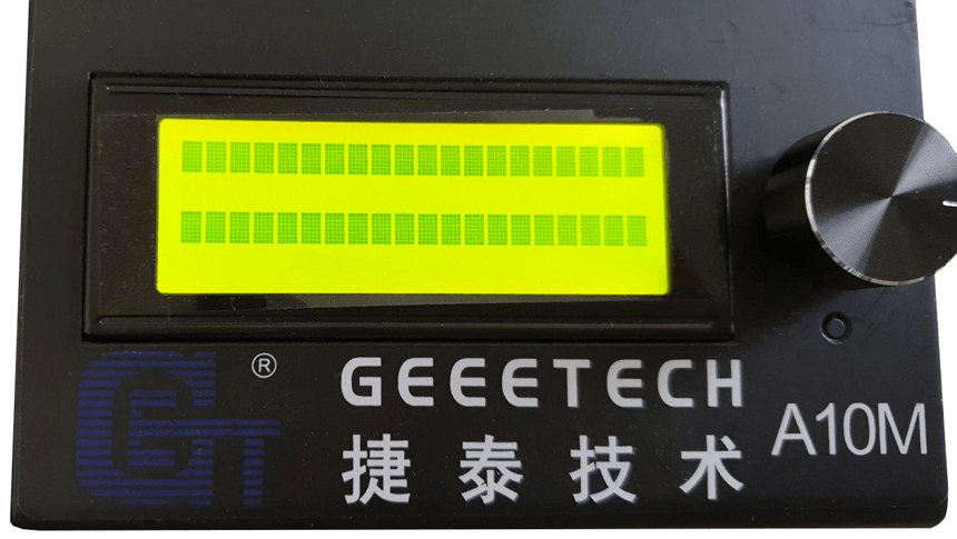
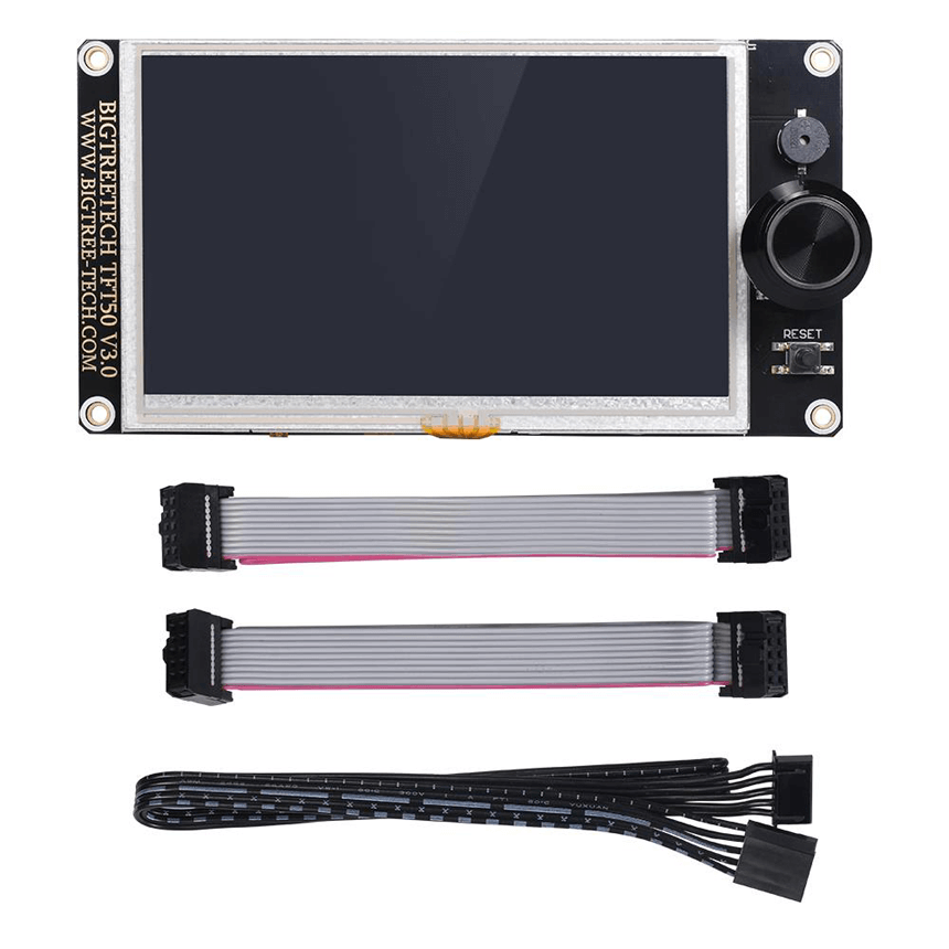
The TFT model comes in several models (V2 without rotary wheel, V3 with wheel) and 3 screen diagonals: 3.5″ TFT35, 5″ TFT50 and 7″ TFT70. I opted for the TFT50 model, the 35 being really too small to use, especially in touchscreen. The 70 is excellent, but its price dissuaded me: €51 on the BTT website, €53 on Aliexpress and €90 on Amazon!
BigTreeTech TFT50 screen
Manufacturer’s website:BigTreeTech TFT 43, 50 or 70 (TFT50: 41€* on the manufacturer’s shop, but the delivery is a bit long)
Purchase on Aliexpress:BigTreeTech TFT50 (46€*), also available on Amazon for models 35 and 70.
*Rates as of November 1, 2024
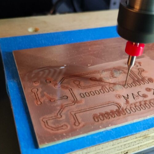
The printer motherboard
The Geeetech GT2560 V3 motherboard is a special version with a specific connector (40-pin ribbon cable) for the display and SD. At first glance, there are no other connectors where you could plug in. If you look closely at the motherboard and study its schematic a little, you will discover some interesting things:
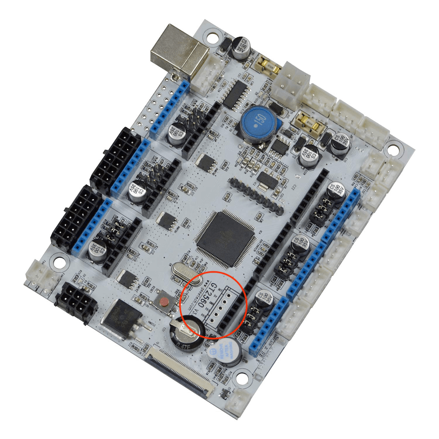
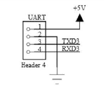
The UART port4 (RXD3/TXD3) is perfectly usable. You just need to solder 4 wires to the pins to be able to connect the ribbon cable provided with the TFT screen from BigtreeTech. Four wires are enough for the TFT, you must use the RS232 link of the BigtreeTech card which has five wires: 5V (+5V), GND (GND), TX (PA2), RX (PA3) Note: the RESET (RST) wire is not used.
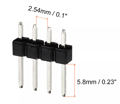
The best solution is to use a 4-pin DIP strip to be soldered with a pitch of 2.54 mm and to use a 4-pin female “Dupont” connector.
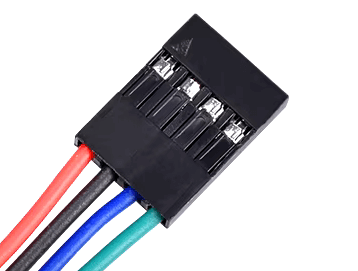
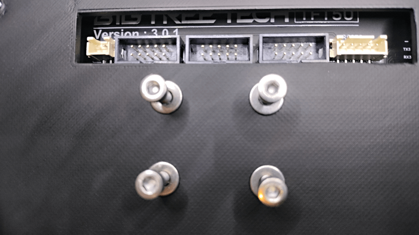
BigtreeTech TFT50 board connectors
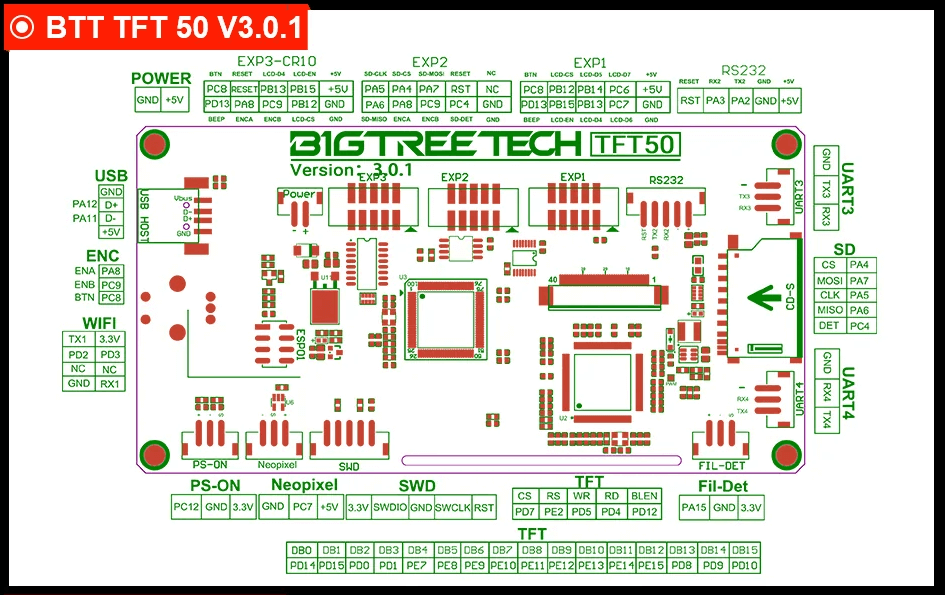
This is the flat ribbon cable that will need to be connected to the RS232 port (top right) and then the wires connected to the Port4 (UART) connector of the GT2560 v3 card of the Geeetech printer. Of course, you will need to cut the ribbon cable and connect the wires correctly so that they correspond to the signals.
Warning: If you looked carefully, you will notice that the TX of the TFT connects to the RX of the card. Same for RX of the TFT which connects to the TX of the card. (for a CR10 pro, there is no TX to RX inversion!)
Note: RX means reception and TX transmission hence the TX of the transmitter to the RX of the receiver and vice versa.
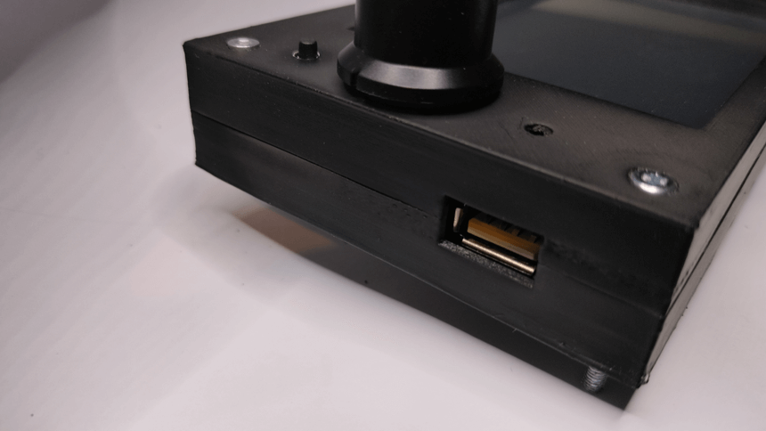
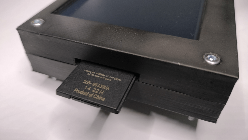
The USB connector on the BigtreeTech board is also functional. You can now start printing from the USB stick connected to it, but I prefer to use the micro-SD card.
BigtreeTech displays are full-fledged microcontrollers and have a 32-bit ARM GD32F205VCT6 processor that is more powerful than the one on the A10’s Geeetech motherboard, an ATMEGA2560. The display’s motherboard practically replaces the printer’s motherboard. On the TFT70 model, the processor is an ARM GD32F407VET6.
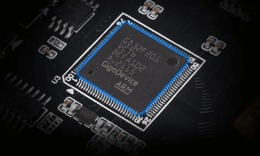
The display processor does most of the work, the printer motherboard just has to chew on Gcode.
ATMEGA2560 (GT2560 card) vs ARM GD32F205VCT6 (BigTreeTech card)
| ATMEGA 2560 | ARM GD32F205VCT6 | |
|---|---|---|
| Architecture | 8 bits | 32 bits |
| clock speed | 16MHz | 120MHz (166MHz on TFT70) |
| Flash Memory (KB) | 32KB (256KB GT2560 V3) | 256KB |
| EEPROM (KB) | 4KB | 128KB |
| SRAM (KB) | 8KB | 128KB |
| I/O | 54 (15 PWM, 16 analog, 23 digital) | +82 |
| ports | 1x USB 2, LCD, | UART, I2C, I2S, SPI, USB 2, SDIO, CAN, TFT |
Firmware change and update
Download and install Microsoft Visual Studio Code (see the explanatory video below for configuration and modification). You must use Vscode, because Arduino is no longer recommended for the latest versions of Marlin (version 2.1.2.2 on my machine)
Marlin firmware v2.1.2.2:download
Bigtreetech firmware
All the info and firmware are on BigtreeTech’s GitHub: link
Don’t forget to replace files configuration.h and configuration_adv.h from Marlin by putting those corresponding to the Geeetech A10 which are in the config/examples folder of the BigtreeTech firmware.
VSCode download link (free software compatible with Linux, Mac & PC): Visual Studio Code
Editing with vscode
See the Explanatory video at the end.
In order to enable this port of the GT2560 card, the firmware must be modified. First, modify line 126 in the file configuration.h and activate the Port_2 3
/**
 * Select a secondary serial port on the board to use for communication with the host.
 * Currently Ethernet (-2) is only supported on Teensy 4.1 boards.
 * :[-2, -1, 0, 1, 2, 3, 4, 5, 6, 7]
 */
#define SERIAL_PORT_2 3 //Modif Touch-screen
#define BAUDRATE_2 115200   // :[2400, 9600, 19200, 38400, 57600, 115200, 250000, 500000, 1000000] Enable to override BAUDRATE
It will also be necessary to modify other lines of the configuration.h file so that the screen is correctly configured for the Geeetech A10 (also valid for the Creality Ender 3). The lines to be modified are annotated:
//Edit touch-screen
// Enable the M48 repeatability test to test probe accuracy
#define Z_MIN_PROBE_REPEATABILITY_TEST //Modif Touch-screen
/**
   * Enable the G26 Mesh Validation Pattern tool.
   */
  #define G26_MESH_VALIDATION //Modif Touch-screen
  #if ENABLED(G26_MESH_VALIDATION)
    #define MESH_TEST_NOZZLE_SIZE    0.4  // (mm) Diameter of primary nozzle.
    #define MESH_TEST_LAYER_HEIGHT   0.2  // (mm) Default layer height for G26.
    #define MESH_TEST_HOTEND_TEMP  190    // (°C) Default nozzle temperature for G26.
    #define MESH_TEST_BED_TEMP      60    // (°C) Default bed temperature for G26.
    #define G26_XY_FEEDRATE         20    // (mm/s) Feedrate for G26 XY moves.
    #define G26_XY_FEEDRATE_TRAVEL 100    // (mm/s) Feedrate for G26 XY travel moves.
    #define G26_RETRACT_MULTIPLIER   1.0  // G26 Q (retraction) used by default between mesh test elements.
  #endif
#define REPRAP_DISCOUNT_FULL_GRAPHIC_SMART_CONTROLLER //Modif Touch-screen
Comment out line 1610 using two slashes // at the beginning of the line:
//#define REPRAP_DISCOUNT_SMART_CONTROLLER //Modif Touch-screen
You will also need to modify a few lines in the configuration_adv.h file.
// Add 'M73' to set print job progress, overrides Marlin's built-in estimate
#define SET_PROGRESS_MANUALLY //Modif Touch-screen
#if ENABLED(SET_PROGRESS_MANUALLY)
  #define SET_PROGRESS_PERCENT            // Add 'P' parameter to set percentage done
  #define SET_REMAINING_TIME              // Add 'R' parameter to set remaining time
  //#define SET_INTERACTION_TIME          // Add 'C' parameter to set time until next filament change or other user interaction
  #define M73_REPORT                    // Modif Touch-screen - Report M73 values to host
  #if BOTH(M73_REPORT, SDSUPPORT)
    #define M73_REPORT_SD_ONLY            // Report only when printing from SD
  #endif
#endif
#define SDCARD_CONNECTION ONBOARD //Modif Touch-screen
#define EMERGENCY_PARSER //Modif Touch-screen
// Some clients will have this feature soon. This could make the NO_TIMEOUTS unnecessary.
#define ADVANCED_OK //Modif Touch-screen
// For serial echo, the number of digits after the decimal point
#define SERIAL_FLOAT_PRECISION 4 //Modif Touch-screen
/**
 * Auto-report temperatures with M155 S<seconds>
 */
#define AUTO_REPORT_TEMPERATURES //Modif Touch-screen
#if ENABLED(AUTO_REPORT_TEMPERATURES) && TEMP_SENSOR_REDUNDANT
  //#define AUTO_REPORT_REDUNDANT // Include the "R" sensor in the auto-report
#endif

/**
 * Auto-report position with M154 S<seconds>
 */
#define AUTO_REPORT_POSITION //Modif Touch-screen

/**
 * Include capabilities in M115 output
 */
#define EXTENDED_CAPABILITIES_REPORT
#if ENABLED(EXTENDED_CAPABILITIES_REPORT)
  #define M115_GEOMETRY_REPORT //Modif Touch-screen
#endif
#define HOST_ACTION_COMMANDS //Modif Touch-screen
#if ENABLED(HOST_ACTION_COMMANDS)
  //#define HOST_PAUSE_M76                // Tell the host to pause in response to M76
  #define HOST_PROMPT_SUPPORT           // Modif Touch-screen - Initiate host prompts to get user feedback
  #if ENABLED(HOST_PROMPT_SUPPORT)
    #define HOST_STATUS_NOTIFICATIONS   // Modif Touch-screen - Send some status messages to the host as notifications
  #endif
  //#define HOST_START_MENU_ITEM          // Add a menu item that tells the host to start
  //#define HOST_SHUTDOWN_MENU_ITEM       // Add a menu item that tells the host to shut down
#endif
Modified configuration.h and configuration_adv.h files for A10: download
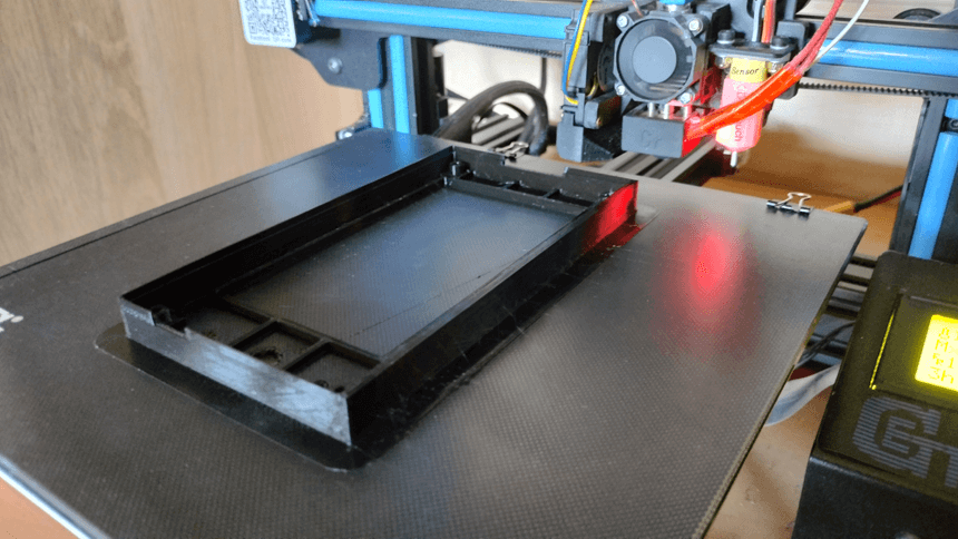
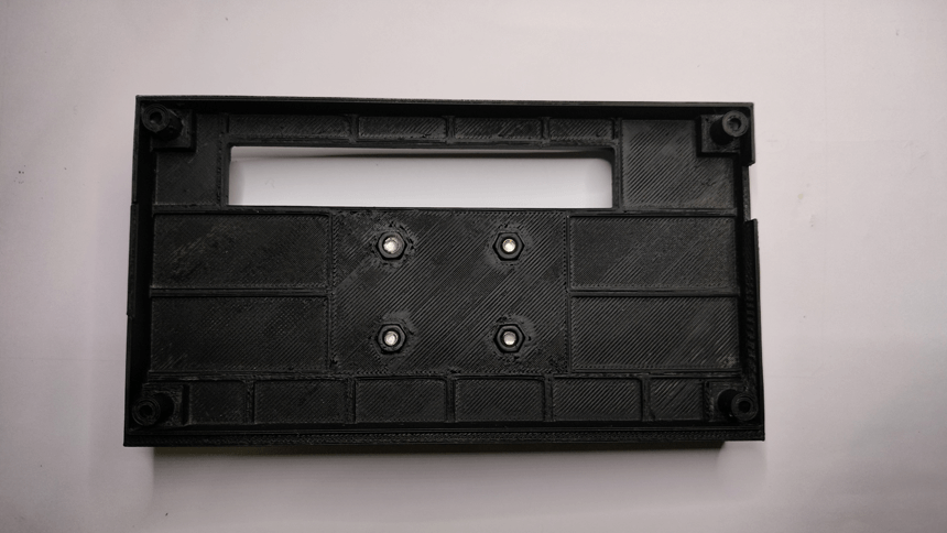
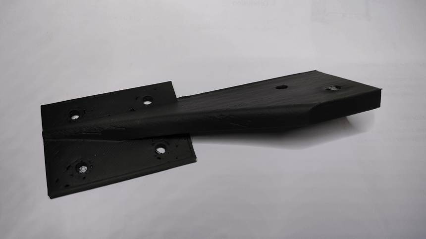
Creation of the case
I designed the case in three parts (case, cover and support) with Solidworks software then made three exports in STL.
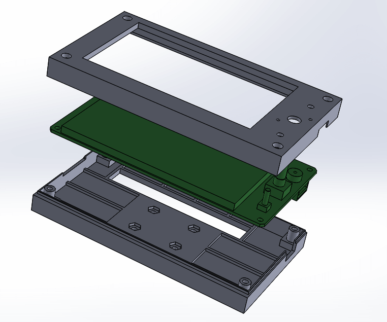
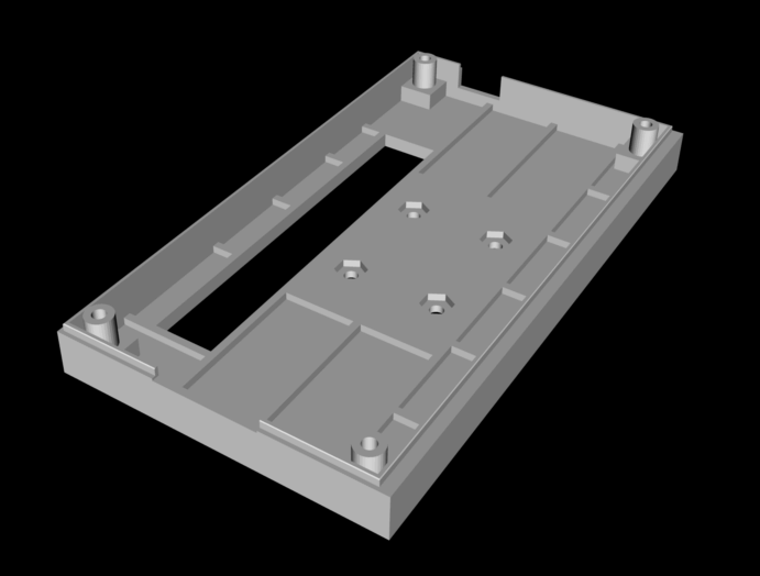
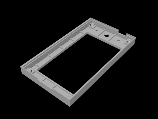
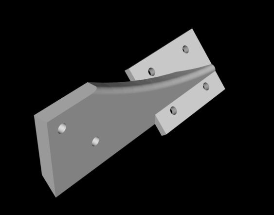
The 3 STL files are available for download here : STL box bigtreetech
Assembly

Firmware modification, update and upload
Follow the excellent tutorial by kaminokgy on Youtube. It is for the TFT35 E3 but it is the same manipulation for the TFT35, TFT50 or TFT70 in v3.
Complete tutorial on Bigtreetech TFT43 V3.0 screen on CR-10S Pro
An excellent Youtube video from Quebecer Jocelyn on the different functions available with this screen.
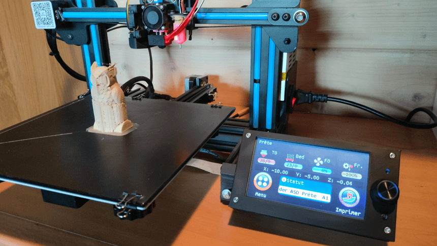
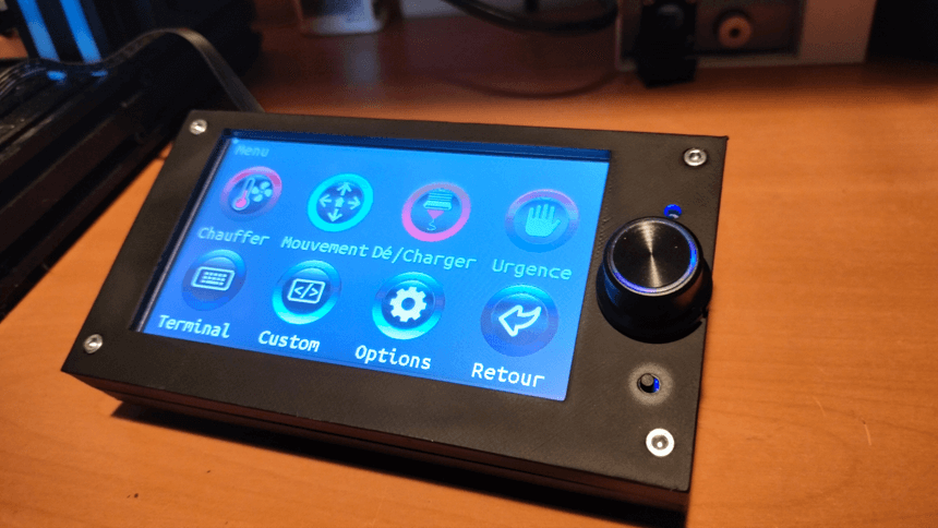
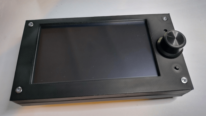
The case finished and mounted on my Geeetech A10